 |
This chapter illustrates how the patterns in this book can be used to solve a variety of integration problems. In order to do so, we examine common integration scenarios and present a comprehensive integration example. As we design the solution to this example, we will express the solution using the patterns contained in this book. At the end of this chapter you will be familiar with about two dozen integration patterns.
The Need for Integration
Enterprises are typically comprised of hundreds if not thousands of applications that are custom-built, acquired from a third-party, part of a legacy system, or a combination thereof, operating in multiple tiers of different operating system platforms. It is not uncommon to find an enterprise that has 30 different Websites, three instances of SAP and countless departmental solutions.
We may be tempted to ask: How do businesses allow themselves to get into such a mess? Shouldn’t any CIO of such an enterprise spaghetti architecture be fired? Well, like in most cases things happen for a reason.
First of all, writing business applications is hard. Creating a single, big application to run a complete business is next to impossible. The ERP vendors have had some success at creating larger-than-ever business applications. The reality, though, is that even the heavyweights like SAP, Oracle, Peoplesoft and the like only perform a fraction of the business functions required in a typical enterprise. We can see this easily by the fact that ERP systems are one of the most popular integration points in today’s enterprises.
Second, spreading business functions across multiple applications provides the business with the flexibility to select the “best” accounting package, the “best” customer relationship management or the order processing system that best suits the business’ needs. One-stop-shopping for enterprise applications is usually not what IT organizations are interested in, nor is possible given the number individual business requirements.
Vendors have learned to cater to this preference and offer focused applications around a specific core function. However, the ever-present urge to add new functionality to existing software packages has caused some functionality spillover amongst packaged business applications. For example, many billing systems started to incorporate customer care and accounting functionality. Likewise, the customer care software maker takes a stab at implementing simple billing functions such as disputes or adjustments. Defining a clear functional separation between systems is hard: is a customer disputing a bill considered a customer care or a billing function?
Users such as customers, business partners and internal users do generally not think about system boundaries when they interact with a business. They execute business functions, regardless of the how many internal systems the business function cuts across. For example, a customer may call to change his or her address and see whether the last payment was received. In many enterprises, this simple request can span across the customer care and billing systems. Likewise, a customer placing a new order may require the coordination of many systems. The business needs to validate the customer ID, verify the customer’s good standing, check inventory, fulfill the order, get a shipping quote, compute sales tax, send a bill, etc. This process can easily span across five or six different systems. From the customer’s perspective, it is a single business transaction.
In order to support common business processes and data sharing across applications, these applications need to be integrated. Application integration needs to provide efficient, reliable and secure data exchange between multiple enterprise applications.
Integration Challenges
Unfortunately, enterprise integration is no easy task. By definition, enterprise integration has to deal with multiple applications running on multiple platforms in different locations, making the term ‘simple integration’ pretty much an oxymoron. Software vendors offer EAI suites that provide cross-platform, cross-language integration as well as the ability to interface with many popular packaged business applications. However, this technical infrastructure presents only a small portion of the integration complexities. The true challenges of integration span far across business and technical issues.
- Enterprise integration requires a significant shift in corporate politics. Business applications generally focus on a specific functional area, such as Customer Relationship Management (CRM), Billing, Finance, etc. This seems to be an extension of Conway's famous law that postulates that "Organizations which design systems are constrained to produce designs which are copies of the communication structures of these organizations." As a result, many IT groups are organized in alignment with these functional areas. Successful enterprise integration does not only need to establish communication between multiple computer systems but also between business units and IT departments -- in an integrated enterprise application groups no longer control a specific application because each application is now part of an overall flow of integrated applications and services.
- Because of their wide scope, integration efforts typically have far-reaching implications on the business. Once the processing of the most critical business functions is incorporated into an integration solution, the proper functioning of that solution becomes vital to the business. A failing or misbehaving integration solution can cost a business millions of Dollars in lost orders, misrouted payments and disgruntled customers.
- One important constraint of developing integration solutions is the limited amount of control the integration developers typically have over the participating applications. In most cases, the applications are “legacy” systems or packaged applications that cannot be changed just to be connected to an integration solution. This often leaves the integration developers in a situation where they have to make up for deficiencies or idiosyncrasies inside the applications or differences between the applications. Often it would be easier to implement part of the solution inside the application “endpoints”, but for political or technical reasons that option may not be available.
- Despite the wide-spread need for integration solutions, only few standards have established themselves in this domain. The advent of XML, XSL and Web services certainly mark the most significant advance of standards-based features in an integration solution. However, the hype around Web services has also given grounds to new fragmentation of the marketplace, resulting in a flurry of new “extensions” and “interpretations” of the standards. This should remind us that the lack of interoperability between “standards-compliant” products was one of the major stumbling blocks for CORBA, which offered a sophisticated technical solution for system integration.
- Also, existing XML Web Services standards address only a fraction of the integration challenges. For example, the frequent claim that XML is the ‘Lingua franca” of system integration is somewhat misleading. Standardizing all data exchange to XML can be likened to writing all documents using a common alphabet, such as the Roman alphabet. Even though the alphabet is common, it is still being used to represent many languages and dialects, which cannot be readily understood by all readers. The same is true in enterprise integration. The existence of a common presentation (e.g. XML) does not imply common semantics. The notion of “account” can have many different semantics, connotations, constraints and assumptions in each participating system. Resolving semantic differences between systems proves to be a particularly difficult and time-consuming task because it involves significant business and technical decisions.
- While developing an EAI solution is challenging in itself, operating and maintaining such a solution can be even more daunting. The mix of technologies and the distributed nature of EAI solutions make deployment, monitoring, and trouble-shooting complex tasks that require a combination of skill sets. In many cases, these skill sets do not exist within IT operations or are spread across many different individuals.
Anyone who has been through an EAI deployment can attest to the fact that EAI solutions are a critical component of today’s enterprise strategies, but make IT life harder, not easier. It’s a long way between the high-level vision of the integrated enterprise (defined by terms such as “Straight-Through-Processing”, “T+1”, “Agile Enterprise”) and the nuts-and-bolts implementations (what parameters did System.Messaging.XmlMessageFormatter take again?).
How Integration Patterns Can Help
There are no simple answers for enterprise integration. In our opinion, anyone who claims that integration is easy must be either incredibly smart (or at least a good bit smarter than the rest of us), incredibly ignorant (OK, let’s say optimistic), or they have a financial interest in making you believe that integration is easy.
Even though integration is a broad and difficult topic, we can always observer some people who are much better at it than others. What do these people know that others don’t? Since there is no such thing as “Teach Yourself Integration in 21 Days” (this book sure ain't!) it is unlikely that these people know all the answers to integration. However, these people have usually solved enough integration problems that they can compare new problems to prior problems they have solved. They know the “patterns” of problems and associated solutions. They learned these patterns over time by trial-and-error or from other experienced integration architects.
The “patterns” are not copy-paste code samples or shrink-wrap components, but rather nuggets of advice that describe solutions to frequently recurring problems. Used properly, the integration patterns can help fill the wide gap between the high-level vision of integration and the actual system implementation.
The Wide World of Integration
We intentionally left the definition of “integration” very broad. To us it means connecting computer systems, companies or people. While this broad definition gives us the convenience of sticking whatever we find interesting into this book, it is helpful to have a closer look at some of the most common integration scenarios. Helping clients design and implement integration solutions, we repeatedly came across the following six types of integration projects:
- Information Portals
- Data Replication
- Shared Business Functions
- Service-Oriented Architectures
- Distributed Business Processes
- Business-to-Business Integration
This list is by no means a complete taxonomy of all things integration but it does help to illustrate the kind of solutions that integration architects build. Many integration projects consist of a combination of multiple types of integration. For example, reference data replication is often required in order to tie applications into a single distributed business process.
Information Portal
Many business users have to access more than one system to answer a specific question or to perform a single business function. For example, to verify the status of an order, a customer service representative may have to access the order management system on the mainframe plus log on to the system that manages orders placed over the Web. Information portals aggregate information from multiple sources into a single display to avoid having the user access multiple systems for information. Simple information portals divide the screen into multiple zones, each of which displays information from a different system. More sophisticated systems provide limited interaction between zones, for example when a user selects an item from a list in zone A, zone B refreshes with detailed information about the selected item. Other portals provide even more sophisticated user interaction and blur the line between a portal and an integrated application.
Data Replication
Many business systems require access to the same data. For example, a customer’s address may be used in the customer care system (when the customer calls to change it), the accounting system (to compute sales tax), the shipping system (to label the shipment) and the billing system (to send an invoice). Many of these systems are going to have their own data stores to store customer related information. When a customer calls to change his or her address all these systems need to change their copy of the customer’s address. This can be accomplished by implementing an integration strategy based on data replication.
There are many different ways to implement data replication. For example, some database vendors build replication functions into the database, we can export data into files and re-import them into the other system, or we can use message-oriented middleware to transport data records inside messages.
Shared Business Function
In the same way that many business applications store redundant data, they also tend to implement redundant functionality. Multiple systems may need to check whether a social-security number is valid, whether the address matches the specified postal code or whether a particular item is in stock. It makes business sense to expose these functions as a shared business function that is implemented once and available as a service to other systems.
A shared business function can address some of the same needs as data replication. For example, we could implement a business function called ‘Get Customer Address’ that could allow other systems to request the customer’s address when it is needed rather than always storing a redundant copy. The decision between these two approaches is driven by a number of criteria, such as the amount of control we have over the systems (calling a shared function is usually more intrusive than loading data into the database) or the rate of change (an address may be needed frequently but change very infrequently).
Service-Oriented Architecture
Shared business functions are often referred to as services. A service is a well-defined function that is universally available and responds to requests from “service consumers”. Once an enterprise assembles a collection of useful services, managing the services becomes an important function. First of all, applications need some form of service directory, a centralized list of all available services. Second, each service needs to describe its interface in such a way that an application can “negotiate” a communications contract with the service. These two functions, service discovery and negotiation, are the key elements that make up a service-oriented architecture.
Service-oriented architectures (SOAs) blur the line between integration and distributed applications. A new application can be developed using existing, remote services that may be provided by other applications. Therefore, calling a service may be considered integration between the two applications. On the other hand a service-oriented architecture usually provides tools that make calling an external service almost as simple as calling a local method (performance considerations aside). Because all services are available in a consistent manner, SOAs are sometimes referred to as “service bus architectures”.
Distributed Business Process
One of the key drivers of integration is the fact that a single business transaction is often spread across many different systems. A previous example showed us that a simple business function such as “place order” can easily touch six or seven systems. In most cases, all relevant functions are incorporated inside existing applications. What is missing is the coordination between the applications. Therefore, we can add a business process management component that manages the execution of a business function across multiple existing systems.
The boundaries between a service-oriented architecture and a distributed business can blur. For example, you could expose all relevant business functions as service and then encode the business process inside an application that accesses all services via an SOA.
Business-to-Business Integration
So far we have mainly considered the interaction between applications and business functions inside an enterprise. In many cases, business functions may be available from outside suppliers or business partners. For example, the shipping company may provide a service for customers to compute shipping cost or track shipments. Or a business may use an outside provider to compute sales tax rates. Likewise, integration frequently occurs between business partners. A customer may contact a retailer to inquire on the price and the availability of an item. In response, the retailer may ask the supplier for the status of an expected shipment that contains the out-of-stock item.
Many of the above considerations apply equally to business-to-business integration. However, communicating across the Internet or some other network usually raises new issues related to transport protocols and security. Also, since many business partners may collaborate in an electronic “conversation” standardized data formats are critically important.
Loose Coupling
One of the biggest buzz words in enterprise architecture and integration is the notion of loose coupling. It is in fact such a popular term that Doug Kaye wrote a whole book titled after this ubiquitous concept [Kaye]. The benefits of loose coupling have been know for quite some time now, but they have taken center stage more recently due to the surging popularity of Web services architectures.
The core principle behind loose coupling is to reduce the assumptions two parties (components, applications, services, programs, users) make about each other when they exchange information. The more assumptions two parties make about each other and the common protocol, the more efficient the communication can be, but the less tolerant the solution is of interruptions or changes because the parties are tightly coupled to each other.
A great example of tight coupling is a local method invocation. Invoking a local method inside an application is based on a lot of assumptions between the called and the calling routine. Both methods have to run in the same process (e.g. a virtual machine) and be written in the same language (or at least use a common intermediate language or byte code). The calling method has to pass the exact number of expected parameters, each using the correct type. The call is immediate, i.e. the called method starts processing immediately after the calling method makes the call. Meanwhile, the calling method will only resume processing when the called method completes (meaning the invocation is synchronous). Processing will automatically resume in the calling method with the next statement after the method call. The communication between the methods is immediate and instantaneous, so neither the caller nor the called method have to worry about security in the form of eavesdropping 3rd parties. All these assumptions make it very easy to write well structured applications that break functionality into individual methods to be called by other methods. A large number of small method allow for flexibility and reuse.
Many integration approaches have aimed to make remote communications simple by packaging a remote data exchange into the same semantics as a local method call. This strategy resulted in the notion of a Remote Procedure Call (RPC) or Remote Method Invocation (RMI), supported by many popular frameworks and platforms: CORBA (see[Zahavi]), Microsoft DCOM, .NET Remoting, or Java RMI, and most recently, RPC-style Web services. The intended upside of this approach is twofold. First, synchronous method-call semantics are very familiar to application developers, so why not build on what we already know. Second, using the same syntax and semantics for both local method calls and remote invocations would allow us to defer the decision about what components should run locally and which ones run remotely until deployment time, leaving the application developer with one less thing to worry about.
The challenge that all these approaches face lies in the fact that remote communication invalidates many of the assumptions that a local method call is based on. As a result, abstracting the remote communication into the simple semantics of a method call can be confusing and misleading. Waldo et al. reminded us back in 1994 that "objects that interact in a distributed system need to be dealt with in ways that are intrinsically different from objects that interact in a single address space" [Waldo]. For example, if we call a remote service to perform a function for us, do we really want to restrict ourselves to only those services that were built using the same programming language as we do? A call across the network also tends to be multiple orders of magnitude slower than a local call. Should the calling method really wait until the called method completes? What if the network is interrupted and the called method is temporarily unreachable? How long should we wait? How can we be sure we communicate with the intended party and not a 3rd party “spoofer”? How can we protect against eavesdropping? What if the method signature (the list of expected parameters) of the called method changes? If the remote method is maintained by a third party or a business partner we no longer have control over such changes. Should we have our method invocation fail or should we attempt to find the best possible mapping between the parameters and still make the call? It becomes quickly apparent that remote integration brings up a lot of issues that a local method call never had to deal with.
In summary, trying to portray remote communication as a variant of a local method invocation is asking for trouble. Such architectures typically result in brittle, hard to maintain and poorly scalable solutions. Many Web services pioneers recently (re-)discovered this fact the hard way.
1 Minute EAI
To show the effects of tightly coupled dependencies and how to resolve them, let’s look at different options of connecting two systems. Let’s assume we are building an on-line banking system that allows customers to deposit money into their account from another bank. To perform this function, the front-end Web application has to be integrated with the back-end financial system that manages fund transfers.
The easiest way to connect the two systems is through the TCP/IP protocol. Every self-respecting operating system or programming library created in the last 15 years is certain to include a TCP/IP stack. TCP/IP is the ubiquitous communications protocol that transports data between the millions of computers connected to the Internet and local networks. Why not use the most ubiquitous of all network protocols to communicate between two applications?
Let’s assume that the remote function that deposits money into a person’s account takes only the person’s name and the Dollar amount as arguments. The following few lines of code then suffice to call such a function over TCP/IP (we chose C#, but this code would look virtually identical in C or Java).
String hostName = "www.eaipatterns.com";
int port = 80;

IPHostEntry hostInfo = Dns.GetHostByName(hostName);
IPAddress address = hostInfo.AddressList[0];

IPEndPoint endpoint = new IPEndPoint(address, port);

Socket socket = new Socket(address.AddressFamily, SocketType.Stream, ProtocolType.Tcp);
socket.Connect(endpoint);

byte[] amount = BitConverter.GetBytes(1000);
byte[] name   = Encoding.ASCII.GetBytes("Joe");

int bytesSent = socket.Send(amount);
bytesSent    += socket.Send(name);

socket.Close();
This code opens a socket connection to the address www.eaipatterns.com and sends two data items (the amount and the customer’s name) across the network. No expensive middleware is required, no EAI tools, RPC toolkits, just 10 lines of code. When we run this code it tells us: “7 bytes sent”. Voila! How can integration be so difficult?
There are a couple of major problems with this integration attempt. One of the strengths of the TCP/IP protocol is its wide support so that we can connect to pretty much any computer connected to the network regardless of the operating system or programming language it uses. However, the platform independence works only for very simple messages: byte streams. In order to convert our data into a byte stream we used the BitConverter class. This class converts any data type into a byte array, using the internal memory representation of the data type. The catch is that the internal representation of an integer number varies with computer systems. For example, .NET uses a 32 bit integer while other systems may use a 64 bit representation. Our example transfers 4 bytes across the network to represent a 32 bit integer number. A system using 64 bits would be inclined to read 8 bytes off the network and would end up interpreting the whole message (including the customer name) as a single number.
Also, some computer systems store their numbers in big-endian format while others store them in little-endian format. A big-endian format stores numbers starting with the highest byte first while little-endian systems store the lowest byte first. PCs operate on a little-endian scheme so that the code passes the following 4 bytes across the network:
232 3 0 0
232 + 3 * 2^8 equals 1000. A system that uses big-endian numbers would consider this message to mean 232* 2^24 + 3 * 2^16 = 3,892,510,720. Joe will be a very rich man! So this approach works only under the assumption that all connected computers represent numbers in the same internal format.
The second problem with this simple approach is that we specify the location of the remote machine (in our case www.eaipatterns.com). The Dynamic Naming Service (DNS) gives us one level of indirection between the domain name and the IP address, but what if we want to move the function to a different computer on a different domain? What if the machine fails and we have to setup another machine? What if we want to send the information to more than one machine? For each scenario we would have to change the code. If we use a lot of remote functions this could become very tedious. So we should find a way to make our communication independent from a specific machine on the network.
Our simple TCP/IP example also establishes temporal dependencies between the two machines. TCP/IP is a connection-oriented protocol. Before any data can be transferred, a connection has to be established first. Establishing a TCP connection involves IP packets traveling back and forth between sender and receiver. This requires that both machines and the network are all available at the same time. If any of the three pieces is malfunctioning or not available due to high load, the data cannot be sent.
Lastly, the simple communication also relies on a very strict data format. We are sending 4 bytes of amount data and then a sequence of characters that define the customer’s account. If we want to insert a third parameter, e.g. the name of the currency, we would have to modify both sender and receiver to use the new data format.
Tightly Coupled Interaction
In summary, our minimalist integration solution is fast and cheap, but it results in a very brittle solution because the two participating parties make the following assumptions about each other:
- Platform Technology – internal representations of numbers and objects
- Location – hard-coded machine addresses
- Time – all components have to be available at the same time
- Data Format – the list of parameters and their types must match
As we stated in the beginning, coupling is a measure of how many assumptions parties make about each other when they communicate. Our simple solution requires the parties to make a lot of assumptions. Therefore, this solution is tightly coupled.
In order to make the solution more loosely coupled we can try to remove these dependencies one by one. We should use a standard data format that is self-describing and platform independent, such as XML. Instead of sending information directly to a specific machine we should send it to an addressable “channel”. A channel is a logical address that both sender and receiver can agree on the same channel without being aware of each other’s identity. Using channels resolves the location-dependency, but still requires all components to be available at the same time if the channel is implemented using a connection-oriented protocol.. In order to remove this temporal dependency we can enhance the channel to queue up sent requests until the network and the receiving system are ready. To support queuing of requests inside the channel, we need wrap data into self-contained messages so that the channel knows how much data to buffer and deliver at any one time. Lastly, the two systems still depend on a common data format. We can remove this dependency by allowing for data format transformations inside the channel. If the format of one system changes we only have to change the transformer and not the other participating systems. This is particularly useful if many applications send data to the same channel.
Loosely Coupled Interaction
Mechanisms such as a common data format, queuing channels, and transformers help turn a tightly coupled solution into a loosely coupled solution. The sender no longer has to depend on the receiver's internal data format not its location. It does not even have to pay attention to whether the other computer is ready to accept requests or not. Removing these dependencies between the systems makes the overall solution more tolerant to change, the key benefit of loose coupling. The main drawback of the loosely coupled approach is the additional complexity. This is no longer a 10-lines-of-code solution! Therefore, we use a message-oriented middleware infrastructure that provides these services for us. This infrastructure makes exchanging data in a loosely coupled way almost as easy as the example we started with. The next section describes the components that make up such a middleware solution.
Is loose coupling the panacea? Like everything else in enterprise architecture, there is no single best answer. Loose coupling provides important benefits such as flexibility and scalability, but it introduces a more complex programming model and can make designing, building and debugging solutions more difficult.
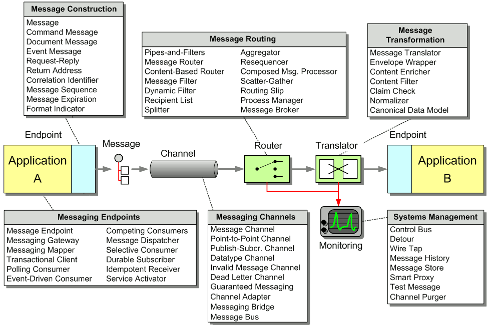
A Loosely Coupled Integration Solution
In order to connect two systems via an integration solution, a number of things have to happen. These things make up what we call middleware – the things that sit between applications.
Invariably, some data has to be transported from one application to the next. This data could be an address record that needs to be replicated, a call to a remote service or a snippet of HTML headed for a portal display. Regardless of the payload, this piece of data needs to be understood by both ends and needs to be transported, usually across a network. Two elements provide this basic function. We need a communications channel that can move information from one application to the other. This channel could be a series of TCP/IP connections, a shared file, a shared database or a floppy disk being carried from one computer to the next (the infamous ‘sneakernet’). Inside this channel we place a message – a snippet of data that has an agreed-upon meaning to both applications that are to be integrated. This piece of data can be very small, such as the phone number of a single customer that has changed, or very large, such as the complete list of all customers and their associated addresses. We call this piece of data a message.
Basic Elements of an Integration Solution
Now that we can send messages across channels we can establish a very basic form of integration. However, we promised that simple integration is an oxymoron, so let’s see what is missing. We mentioned before that integration solutions often have limited control over the applications they are integrating, such as the internal data formats used by the applications. For example, one data format may store the customer name in two fields, called FIRST_NAME and LAST_NAME, while the other system may use a single field called Customer_Name. Likewise, one system may support multiple customer addresses while the other system only supports a single address. Because the internal data format of an application can often not be changed the middleware needs to provide some mechanism to convert one application’s data format in the other’s. We call this step translation.
So far we can send data from one system to another and accommodate differences in data formats. What happens if we integrate more than two systems? Where does the data have to be moved? We could expect each application to specify the target system(s) for the data it is sending over the channel. For example, if the customer address changes in the customer care system we could make that system responsible for sending the data to all other systems that store copies of the customer address. As the number of systems increases this becomes very tedious and requires the sending system to have knowledge about all other systems. Every time a new system is added, the customer care system would have to be adjusted to the new environment. Things would be a lot easier of the middleware could take care of sending messages to the correct places. This is the role of a routing component such as a message broker.
Integration solutions can quickly become complex because they deal with multiple applications, data formats, channels, routing and transformation. All these elements may be spread across multiple operating platforms and geographic locations. In order to have any idea what is going on inside the system we need a systems management function. This subsystem monitors the flow of data, makes sure that all applications and components are available and reports error conditions to a central location.
Our integration solution is now almost complete. We can move data from one system from another, accommodate differences in the data format, route the data to the required systems and monitor the performance of the solution. So far we assumed that an application sends data as a message to the channel. However, most packaged and legacy applications and many custom applications are not prepared to participate in an integration solution. We need a message endpoint to connect the system explicitly to the integration solution. The endpoint can be a special piece of code or a Channel Adapter provided by an integration software vendor.
Widget-Gadget Corp -- An Example
The best way to understand message-based integration solutions is by walking through a concrete example. Let’s consider Widgets & Gadgets ‘R Us (WGRUS), an on-line retailer that buys widgets and gadgets from manufacturers and resells them to customers.
WGRUS Ecosystem
For this example, we assume that the solution needs to support the following requirements. Naturally, we simplified the requirements a bit for sake of brevity, but nevertheless these types of requirements occur frequently in real businesses.
- Take Orders: Customers can place orders via Web, phone or fax
- Process Orders: Processing an order involves multiple steps, including verifying inventory, shipping the goods and invoicing the customer
- Check Status: Customers can check the order status
- Change Address: Customers can use a Web front-end to change their billing and shipping address
- New Catalog: The suppliers update their catalog periodically. WGRUS needs to update its pricing and availability based in the new catalogs.
- Announcements: Customers can subscribe to selective announcements from WGRUS.
- Testing and Monitoring: The operations staff needs to be able to monitor all individual components and the message flow between them.
We will tackle each of these requirements separately and describe the solution alternatives and trade-offs using the pattern language introduced in this book.
Internal Systems
Like in most integration scenarios, WGRUS is not a so-called “green field” implementation, but rather the integration of an existing IT infrastructure comprised of a variety of packaged and custom applications. The fact that we have to work with existing applications often makes integration work challenging. In our example WGRUS runs the following systems (see picture).
WGRUS IT Infrastructure
WGRUS has four different channels to interact with customers. Customers can visit the company Web site, call the customer service representative at the call center or submit orders via fax. Customers can also receive notifications via e-mail.
WGRUS’ internal systems are comprised of the accounting system, which also includes billing functions, the shipping system that computes shipping charges and interacts with the shipping companies. For historic reasons, WGRUS has two inventory and catalog systems. WGRUS used to sell only widgets but acquired another retailer that sells gadgets. WGRUS decided it will be less expensive to operate parallel systems than trying to rewrite both systems into a single system.
Taking Orders
The first function we want to implement is taking orders. Taking orders is a good thing because they bring revenue. However, placing orders is currently a tedious manual process so that the cost incurred with each order is high. In fact, on orders below $20 WGRUS hardly makes any money because any potential profit is eaten up by labor cost processing the order.
The first step to streamlining order processing is to unify taking orders. A customer can place orders over one of three channels: Web site, call center or fax. Unfortunately, each system is based on a different technology and stores incoming orders in a different data format. The call center system is a packaged application while the Web site is a custom J2EE application. The inbound fax system requires manual data entry into a small Microsoft Access application. We want to treat all orders equally, regardless of their source. For example, a customer should be able to place an order via the call center and check the order status on the Web site.
Because placing an order is an asynchronous process that connects many systems, we decide to implement a message-oriented middleware solution to streamline the order entry process. Because the packaged call center application was not developed with integration in mind, we connect it to the messaging system using a Channel Adapter. A Channel Adapter is a component that can attach to an application and publish messages to a Message Channel whenever an event occurs inside the application. With some Channel Adapters, the application may not even be aware of the presence of the adapter. For example, a database adapter may add triggers to specific tables so that every time the application inserts a row of data a message is sent to the Message Channel. Channel Adapters can also work in the opposite direction, consuming messages off a Message Channel and triggering an action inside the application in response.
We use the same approach for the inbound fax application, connecting the Channel Adapter to the application database. Because the Web application is custom-built we implement the Endpoint code inside the application. We use a Messaging Gateway to isolate the application code from the messaging-specific code.
Taking Orders From Three Difrerent Channels
Because each system uses a different data format for the incoming orders we use three Message Translators to convert the different data formats into a common New Order message that follows a Canonical Data Model. A Canonical Data Model defines message formats that are independent from any specific application so that all applications can communicate with each other in this common format. If the internal format of an application changes, only the Message Translator between the affected application and the coming Message Channel has to change while all other applications and Message Translators remain unaffected. Using a Canonical Data Model means that we deal with two types of messages: canonical (public) messages and application-specific (private) messages. Application-specific messages should not be consumed by any other component except the related application and the associated Message Translator. To reinforce this policy we name application-specific Message Channels starting with the name of the application, e.g. WEB_NEW_ORDER. Channels carrying canonical messages are named after the intent of the message without any prefix, e.g. NEW_ORDER.
We connect each Channel Adapter to the Message Translator via a Point-to-Point Channel because we want to be sure that each order message is consumed only once. We could get away without using a Message Translator for the Web Interface if we programmed the transformation logic into the Gateway. However, hand-coding transformation functions can be tedious and error prone and we prefer to use a consistent approach. The additional Message Translator also allows us to shield the New Order flow from minor changes in the Web Interface data format. All Message Translators publish to the same NEW_ORDER Point-to-Point Channel so that orders can be processed off this channel without regard to the order’s origin.
The NEW_ORDER Message Channel is a so-called Datatype Channel because it carries messages of only one type, i.e. new orders. This makes it easy for message consumers to know what type of message to expect. The New Order message itself is designed as a Document Message. The intent of the message is not to instruct the receiver to take a specific action, but rather to pass a document to any interested recipient who is free to decide how to process document.
Processing Orders
Now that we have a consistent order message that is independent from the message source we need to process orders. In order to fulfill an order we need to complete the following steps:
- Verify the customer’s credit standing. If the customer has outstanding bills, we want to reject the new order.
- Verify inventory. We can’t fulfill orders for items that are not in stock.
- If the customer is in good standing and we have inventory we want to shop the goods and bill the customer.
We can express this sequence of events using a UML activity diagram. Activity diagrams have relatively simple semantics and are a good tool to depict processes that include parallel activities. Subsequent activities are connected by simple arrows. Parallel activities are connected by a thick black bar representing fork and join actions. A fork action causes all connected activities to start simultaneously while the join action only continues after all incoming activities have been completed.
The activity diagram executes the “Check Inventory” task and the “Verify Customer Standing” task in parallel. The join bar waits until both activities are completed before it allows the next activity to start. The next activity verifies the results of both steps – do we have inventory and is the customer in good standing? If both conditions are fulfilled, the process goes on to fulfill the order. Otherwise, we transition to an exception handling activity. For example, we may call the customer to remind them to pay the last invoice or send an e-mail letting him or her know that the order will be delayed. Because this book focuses on the design aspects of message-oriented integration rather than workflow modeling, we leave the details of the exception handling process aside for now. For a very good discussion of workflow architecture and workflow modeling we refer you to [Leyman] and [Sharp].
Activity Diagram for Order Processing
It turns out that the activities map relatively nicely to the systems in WGRUS’ IT department. The Accounting system verifies the customer’s credit standing, the inventory systems check the inventory and the shipping system initiates the physical shipping of goods. The accounting system also acts as the billing system and sends invoices. The order processing function is a typical implementation of a distributed business process.
To convert the logical activity diagram into an integration design, we use a Publish-Subscribe Channel to implement the fork action and an Aggregator to implement the join action. A Publish-Subscribe Channel sends a message to all active consumers while an Aggregator receives multiple incoming messages and combines them into a single outgoing message (see picture):
Order Processing Implementation using Asynchronous Messaging
The Aggregator combines the results from both messages and passes the resulting message to a Content-Based Router. A Content-Based-Router is a component that consumes a message and publishes it unmodified to a choice of other channels based on rules coded inside the router. The Content-Based-Router is equivalent to the branch in a UML activity diagram. In this case, if both the inventory check and the credit check have been affirmative, the Content-Based Router forwards the message to the VALIDATED_ORDER channel. If the customer is not in good standing or we have no inventory on hand, it forwards the message to the INVALID_ORDER process. The exception process (not shown in the picture) listens to messages on this channel and notifies the customer of the rejected order.
As we learned in the requirements section, WGRUS has two inventory systems, one for widgets and one for gadgets. As a result, we have to route the request for inventory to the correct system. Because we want to hide the peculiarities of the inventory systems from the other systems, we insert a Content-Based Router that routes the message to the correct system based on the type of item ordered (see picture). For example, all incoming messages with an item number starting with ‘W’ are routed to the widget inventory system and all orders with an item number starting with ‘G’ are routed to the gadget inventory system.
Routing the Inventory Request
Note that the intent of messages on the Point-to-Point Channels between the Content-Based Router and the inventory systems is different from the previous channel. These channels contain Command Messages, messages that instruct the system to execute the specified command, in this case verifying the inventory of an item.
Because the widget inventory system and the gadget inventory system use different internal data formats we again insert Message Translators to convert from the canonical New Order message format into a system-specific format. Using Message Translators with each originating system (Web Interface, call center, inbound fax) and each target system (widget inventory and gadget inventory) allows us to decouple changes between the systems. For example, if we added another way of placing orders (e.g. ordering by e-mail), none of the other systems would be affected. The price we pay for this flexibility is the fact that we translate each message twice, once at the source and once at the destination.
What happens if the order item starts neither with ‘W’ nor with ‘G”? The Content-Based Router routes the message to the INVALID_ORDER channel so that the invalid order can be processed accordingly, e.g. by notifying the customer. This channel is a typical example of an Invalid Message Channel. This is example highlights the fact that the meaning of a message changes depending what channel it is on. Both the NEW_ORDER channel and the INVALID_ORDER channel transport the same type of message, but in one case a new order is being processed while in the other case the order is deemed invalid.
So far, we have assumed that each order can only contain a single item. This would be pretty inconvenient for our customers because they would have to place a new order for each item. Also, we would end up shipping multiple orders to the same customer and incur unnecessary shipping costs. However, if we allow multiple items inside an order, which inventory system should verify the inventory for this order? We could use a Publish-Subscribe Channel to send the order to each inventory system to pick out the items that it can process. But what would then happen to invalid items? How would we notice that neither inventory system processed the item? We want to maintain the central control the Content-Based Router gives us, but we need to be able to route each order item individually.
Therefore, we insert a Splitter, a component that breaks a single message into multiple individual messages. In our case, the Splitter splits a single Order message into multiple Order Item message. Each Order Item message can then be routed to the correct inventory system using a Content-Based Router (see below).
Processing Order Items Individually
Naturally, when the inventory for all items has been verified, we need to recombine the messages into a single message. We already learned that the component that can combine multiple messages into a single message is the Aggregator. Using both a Splitter and an Aggregator, we can logically separate the message flow for order items from that for orders.
When designing an Aggregator, we have to make three key decisions:
- Which messages belong together (“correlation”)?
- How do we determine that all messages are received (the “completeness condition”)?
- How do we combine the individual messages into one result message (the “aggregation algorithm”)?
We can’t correlate order items by the customer ID because a customer may place multiple orders in short succession. Therefore, we need a unique order ID for each order. We accomplish this by inserting a Content Enricherinto the Taking Orders solution (see picture). A Content Enricheris a component that adds missing data items to an incoming message.
Taking Orders With Enricher
Now that we have an order ID to correlate order item messages, we need to define the completeness condition and the aggregation algorithm. Because we route all messages including invalid items to the Aggregator, the Aggregator can simply use the number of items in the order (one of the fields in the order message) to count until all order items arrive. The aggregation algorithm is similarly simple. The Aggregator concatenates all item messages back into a single order message and publishes it to the VALIDATED_ORDER channel.
The combination of a Splitter, a Router and an Aggregator is fairly common. We refer to it as a Composed Message Processor. To simplify the picture, we insert the symbol for a Composed Message Processor into the original message flow diagram:
Revised Order Process Implementation
Checking Status
Despite connecting the systems via messaging channels, fulfilling an order can take some amount of time. For example, we may be out of a certain item and the inventory system may be holding the inventory check message until new items arrive. This is one of the advantages of asynchronous messaging: the communication is designed to happen at the pace of the components. While the inventory system is “holding” the message, the accounting system can still verify the customer’s credit standing. Once both steps are completed, the Aggregator publishes the Validated Order message to initiate shipment and invoicing.
A long-running business process also means that both customers and managers are likely to want to know the status of a specific order. For example, if certain items are out of inventory, the customer may decide to process just those items that are in stock. Or if the customer has not received the goods it is useful if we can tell him or her that the goods are on their way (including the shipping company’s tracking number) or that there is an internal delay in the warehouse.
Tracking the status of an order with the current design is not so easy. Related messages flow through multiple systems. In order to ascertain the status of the order in the sequence of steps we would have to know the “last” message related to this order. One of the advantages of a Publish-Subscribe Channel is that we can add additional subscribers without disturbing the flow of messages. We can use this property to listen in to new and validated orders and store them into a Message Store. We could then query the Message Store database for the status (see picture):
Adding a Message Store To Track Order Status
In situations where we use a Point-Point-Channel, we cannot simply add a subscriber to the channel because in a Point-to-Point Channel, each message can only be consumer by a single subscriber. However, we can insert a Wire Tap, a simple component that consumes a message off one channel and publishes it to two channels. We can then use the second channel to send messages to the Message Store (see picture).
Tracking Messages with a Wire Tap
Storing message data in a central database has another significant advantage. In the original design each message had to carry all relevant data in order to continue processing the message down the line. For example, the ‘Verify Customer Standing’ may have to pass through all sorts of customer data even though it may only require the customer ID. This additional data is necessary so that the resulting message still contains all data from the original order message. Storing the New Order message in a Message Store has the advantage that all subsequent components can refer to the Message Store for important message data without all intermediate steps having to carry the data along (we will later to this function as Claim Check - messages can “check” data for later retrieval).
Now the Message Store is responsible for maintaining data related to the new message as well as the progress of the message within the process. This data gives us enough information to use the Message Store to determine the next required steps in the process rather than connecting components with fixed Message Channels. For example, if the database contains reply messages from both the inventory systems and the billing system, we can conclude that the order has been validated and send a message to the Shipping and billing system. Instead of making this decision in a separate Aggregator component, we can do it right in the Message Store. Effectively, we are turning the Message Store into a Process Manager.
A Process Manager is a central component that manages the flow of messages through the system. The Process Manager provides two main functions:
- Storing data between messages
- Keeping track of progress and determining the next step
Processing Orders With a Process Manager
This architecture turns the individual systems (e.g. the inventory systems) into Shared Services that can be accessed by any process. This increases reuse and allows for rapid changes and maintenance. The services themselves can still be composed out of multiple steps, wired together via a message flow (for example, using a Composed Message Processor to check inventory status for each order item), or orchestrated via a Process Manager.
The Process Manager itself uses a persistent store (typically files or a relational database) to store data associated with each process instance. In order to allow the Web Interface to query the status of an order we could send a message to the Process Manager or the order DB. However, checking status is a synchronous process – the customer expects the response right away. Because the Web Interface is a custom application, we decide to access the Order Database directly to query the order status. This form of Shared Database is the simplest and most efficient approach and we are always ensured that the Web Interface displays the most current status. The potential downside of this approach is the fact that the Web Interface is tightly coupled to the database, a trade-off that we are willing to take.
The new architecture exposes all services to a common services bus so that they can be invoked from any other component. If we add facilities to lookup (“discover”) a service from a service registry, we can turn the WGRUS IT infrastructure into a Service-Oriented Architecture. In order to participate in a Service-Oriented Architecture, each service has to provide additional functions. For example, each service has to expose an interface contract that describes the functions provided by the service. Each request-reply service also needs to support the concept of a Return Address. A Return Address allows the caller (the “service consumer”) to specify the channel where the service should send the reply message. This is important to allow the service to be reused in different contexts, each of which may require its own channel for reply messages.
One difficulty in enabling these service functions is that many legacy systems were not build with features such as Return Address in mind. Therefore, we “wrap” access to the legacy system with a Smart Proxy. This Smart Proxy enhances the basic system service with additional capability so that it can participate in a Service-Oriented Architecture. To do this, the Smart Proxy intercepts both request and reply messages to and from the basic service (see picture).
Inserting a Smart Proxy to Turn a Legacy System Into a Shared Service
The Smart Proxy can store information from the request message (e.g. the Return Address specified by the requestor) and use this information to process the reply message, (e.g. route it to the correct reply channel). A Smart Proxy is also very useful to track quality of service (e.g. response times) of an external service.
Change Address
WGRUS needs to deal with a number of addresses. For example, the invoice has to be sent to the customer’s billing address while the goods are shipped to the shipping address. We want to allow the customer to maintain all these addresses through the Web Interface to eliminate unnecessary manual steps.
We can choose between two basic approaches to get the correct billing and shipping addresses to the billing and shipping systems:
- Include address data with the New Order message
- Replicate address data to other systems
The first option has the advantage that we can use an existing integration channel to transport the additional information. A potential downside is the additional data flowing across the middleware infrastructure. We pass the address data along with every order even though the address may change much less frequently.
Because the billing and shipping systems are packaged applications they were not designed with integration in mind. As such, they are unlikely to be able to accept addresses with a new order but rather use the address that is stored in their local database. In order to enable the systems to update the address with the New Order message we need to execute two functions in the billing system (and the shipping system): first, we need to update the address, and then we need to send the bill (or ship the goods). Because the order of the two messages matters we insert a simple Process Manager component that receives a New Order message (which includes the current shipping and billing address0 and publishes two separate messages to the billing (or shipping) system (see diagram).
Including Address Data in the New Order Message
We update the address directly into the system database using a database Channel Adapter. Sending the goods or producing an invoice has to invoke the applications’ business logic. Therefore, we connect to the applications’ business tiers and invoke the correct API function when a message is received.
We need to keep in mind that the Channel Adapters require messages to be formatted in the proprietary formats used by the applications (using so-called private messages). Because the New Order message arrives in the canonical message format we need to perform a translation between the two formats. We could build the transformation into the Process Manager but we actually prefer external Message Translators so that the logic inside the Process Manager is not affected by the possibly complicated data format required by the applications.
The second option uses data replication to propagate address changes to all affected systems independently of the New Order process. Whenever the address information changes in the Web interface we propagate the changes to all interested systems using a Publish-Subscribe Channel. The systems store the updated address internally and use it when an order message arrives. This approach reduces message traffic (assuming customers change addresses less frequently than they place orders). It can also reduce coupling between systems. Any system that uses an address can subscribe to the ADDRESS_CHANGE channel without affecting any other systems. The potential downside is that we have to build another interface function for the billing and shipping systems to enable them to consume address change messages.
Because we are dealing with multiple types of addresses (shipping and billing addresses) we need to make sure that only the right type of address is stored in each system. We need to avoid sending an address change message to the shipping system if the address is a billing address. We accomplish this by using Message Filters that only pass messages matching certain criteria (see diagram).
We also use Message Translators to translate the generic Address Change message into the specific message format used by the applications. In this case we do not use a Message Translator for the Web Interface because we define the Canonical Data Model as equal to the format of the Web Interface application. This could limit out flexibility if we want to introduce other ways of changing addresses in the future, but for now it is sufficient.
Propagating Address Changes via a Separate Publish-Subscribe Channel
Both the shipping and the billing system store addresses in a relational database so that we use a database Channel Adapter to update the data in each system.
How do we decide between the two options? In our situation the message traffic is not much of a concern because we only process a few hundred orders a day, so either solution would work well. The main decision driver is going to be the internal structure of the applications. We may not be able to insert the addresses directly into the database, but rather through the applications’ business layer. In this case the applications may perform additional validation steps and record the address change activity. The system may even be programmed to e-mail a confirmation message to the customer every time the address changes. This would get very annoying if the update the address with every order. Such a condition would favor propagating address changes using dedicated messages that are sent only when the customer actually changes the address.
In general we prefer well-defined, self-contained business actions such as “Change Address” and “Place Order” because they give us more flexibility in orchestrating the businesses processes. It all comes down to a question of granularity and the associated trade-offs. Fine-grained interfaces can lead to sluggish systems due to an excessive number of remote calls being made or messages being sent. For example, imagine an interface that exposes a separate method to change each address field. This approach would be efficient if the communication happens inside a single application – you only update those fields that changed. In an integration scenario sending six or seven messages to update an address would be a significant overhead plus we would have to deal with synchronizing the individual messages. Fine-grained interfaces also lead to tight coupling. If we change the address format, we have to define new message formats and change all other applications to send an additional message.
Coarse grained interfaces solve these issues. We send fewer messages and are therefore more efficient and less tightly coupled. However, interfaces that are too coarse can limit our flexibility. If Send Invoice and Change Address are combined into one external function, will we never need to change an address without sending a bill? So as always the best answer is the happy medium and depends on the specific trade-offs at work in the real-life scenario.
New Catalog
In order for customers to place orders they need to see the currently offered items and their prices on-line. WGRUS’ catalog is driven by the offerings from the respective suppliers. However, one of the services that WGRUS provides to its customers is allowing them to view widgets and gadgets on the same site and to order both types of items in a single order. This function is an example of an Information Portal scenario – we combine information from multiple sources into a single view.
It turns out that both suppliers update their product catalog once every 3 months. Therefore, it makes relatively little sense to create a real-time messaging infrastructure to propagate catalog changes from the suppliers to WGRUS. Instead, we use File Transfer integration to move catalog data from suppliers to WGRUS. The other advantage of using files is that they are easily and efficiently transported across public networks using FTP or similar protocols. In comparison, most asynchronous messaging infrastructures do not work well over the public Internet.
We still can use Translators and Adapters to transform the data to our internal catalog format. However, these Translators process a whole catalog at once instead of one item at a time. This approach is much more efficient if we are dealing with large amounts of data in the same format.
Updating Catalog Data via File Transfer
Announcements
In order to improve business, we want to announce specials to our customers every once in a while. In order to not annoy the customers, we allow the customer to only receive messages that are of interest to them. We also want to target specific messages to a specific subset of customers. For example, we may announce special deals only to preferred customers. When we need to send information to multiple recipients, a Publish-Subscribe Channel immediately comes to mind. However, a Publish-Subscribe Channel has some disadvantages. First, it allows any subscriber to listen to the published messages without the publisher’s knowledge. For example, we would not want smaller customers to receive special offers intended for high-volume customers. The second downside of Publish-Subscribe Channels is that they work efficiently only on local networks. If we send data across wide-area networks the Publish-Subscribe Channel we have to send a separate copy of the message to each recipient. If a recipient is not interested in the message we would have incurred unnecessary network traffic.
Therefore, we should look for a solution that allows subscribers to issue their subscription preferences and then send individual messages only to interested (and authorized) customers. In order to perform this function we use a Dynamic Recipient List. A Dynamic Recipient List is the combination of two Message Routing patterns. A Recipient List is a router that propagates a single message to a set of recipients. The main difference between the Recipient List and a Publish-Subscribe Channel is that the Recipient List addresses each recipient specifically and therefore has tight control over who receives messages. A Dynamic Router is a router whose routing algorithm can change based on control messages. These control messages can take the form of subscription preferences issued by the subscribers. Combining these two patterns results in a Dynamic Recipient List.
Sending Announcements With a Dynamic Recipient List
If customers receive announcements via e-mail, the implementation of these patterns can use the mailing lists features typically supplied by e-mail systems. Each recipient channel is then identified by an e-mail address. Likewise, if customers prefer to receive announcements via a Web services interface, each recipient channel is implemented by a SOAP request and the channel address is the URI of the Web service. This example illustrates that the patterns we use to describe the solution design are independent of a specific transport technology.
Testing and Monitoring
Monitoring the correct execution of messages is a critical operations and support function. The Message Store can provide us with some important business metrics such as the average time to fulfill an order. However, we may need for more detailed information for the successful operation of an integration solution. Let’s assume we enhance our solution to access an external credit agency to better assess our customer’s credit standing. Even if we show no outstanding payments we may want to decline a customer’s order if the customer’s credit ranking is particularly poor. This is especially useful for new customers. Because the service is provided by an outside provider we are being charged for its use. To verify the provider’s invoice we want to track our actual usage and reconcile the two reports. We cannot simply go by the number of orders because the business logic may not request an external credit check for long-standing customers. Also, we have a Quality of Service (QoS) with the external provider. If the response time exceeds a specified time, we do not have to pay for the request.
To make sure we are being billed correctly we want to track the number of requests we made and the time it takes for the associated response to arrive. We have to be able to deal with two specific situations. The external service can process more than one request at a time, so we need to be able to match up request and reply messages. Second, since we treat the external service as a shared service inside our enterprise we want to allow the service consumer to specify a Return Address, the channel where the service should send the reply message. It could be difficult to match request and reply messages if we don’t know which channel the reply message is on.
Once again the Smart Proxy is the answer. We insert the Smart Proxy between any service consumer and the external service. We replace the Return Address specified by the service consumer with a fixed reply channel. We store the original Return Address inside the Smart Proxy so that it can forward the reply message to the channel specified by the consumer. The Smart Proxy also measures the time elapsed between request and reply message from the external service. The Smart Proxy publishes this data to the Control Bus. The Control Bus is connected to a management console that collects metrics from many different components.
Inserting a Smart Proxy to Track Response Times
We also want to make sure that the external credit service is working correctly. The Smart Proxy can report cases where no reply message is received within a specified time-out period to the management console. Much harder to detect are cases where the external service returns a reply message but the results in the message are incorrect. For example is the external service malfunctions and returns a credit score of zero for every customer we would end up denying every order. There are two mechanisms that can help us protect against such a scenario. First, we can periodically inject a Test Message into the request stream. This Test Message requests the score for a specific person so that the result is known. We can then use a Test Data Verifier to not only check the fact that a reply was received but also the accuracy of the message content. Because the Smart Proxy supports Reply Addresses the Test Data Generator can specify a special reply channel to separate test replies from regular replies (see picture).
Inserting Test Messages to Verify Accurate Results
Another effective strategy to detect malfunctioning services that return messages in a valid format but with bad data is to take a statistical sample. For example, we may expect to decline an average of less than one in 10 orders due to the customer’s poor standing. If we decline more than 5 orders in a row this may be an indication that an external service or some business logic is malfunctioning. The management console could e-mail the five orders to an administrator who can then take a quick look at the data to verify whether the rejections were justified.
Summary
We have walked through a fairly extensive integration scenario using different integration strategies such as File Transfer, Shared Database and asynchronous Messaging. We routed, split and aggregated messages. We also added functions to monitor the correct operation of the solution. While the requirements for this example were admittedly simplified the issues and design trade-offs we had to consider are very real. The solution diagrams and descriptions highlight how we can describe a solution in a vendor-and technology-neutral language that is much more accurate than a high-level sequence diagram.
The integration scenario in this chapter focused primarly on how to connect existing applications. For a detailed description on how to publish and consume messages from inside a custom application see the examples in Chapter 6 and Chapter 9 (see Introduction to Simple Messaging Examples and Introduction to Composed Messaging Examples)
The remainder of the book contains detailed descriptions and code examples for each of the patterns that we used in our solution design. The patterns are categorized by their primary intent between base patterns, channel patterns, message patterns, routing patterns, transformation patterns, endpoint patterns and system management patterns. This arrangement makes it easy to read all patterns in sequence or look up individual patterns as a reference.
Integration Pattern Language